


Our systems are engineered to perform, engineered to last. “
Daniel Schimelman | CEO ROEMHELD North America


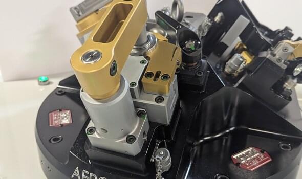
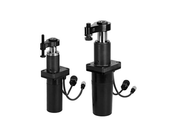
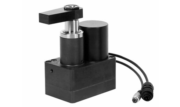
POWER WORKHOLDING
Quick Ship
Over 200 of our most popular products available for immediate shipment from St. Louis, Missouri.
ROEMHELD North America’s Quick Ship products are a collection of our most popular core power workholding products that are in stock and ready to ship.
This collection consists of our most robust and popular products, including Threaded-Body, Block, Pull-Type, Hollow-Piston, and Low-Block Clamping Cylinders; Hinge, Compact, and Compact Swing Clamps; Threaded-Body Work Supports, and more.


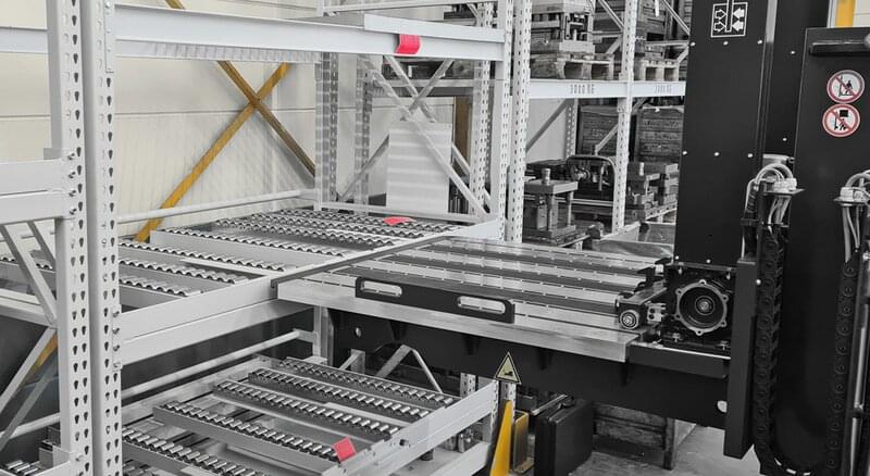


Applications - Weber
Set-up, accelerate and automate from batch size one“
with a HILMA vice for 80 percent of all components
Weber is on course for success. The fast-growing company says it is the international market leader in machines for high-performance industrial slicing of sausage, ham and cheese.
read more


HAPPY TO HELP
Let's Collaborate
Our Application Engineers in North America can address your unique challenges and leverage our expertise to find cost-effective solutions from your application.
We offer Free Quotes, Process Evaluations, and Design Concepts.
Registration
New here?
Take advantage of the free benefits of our login area:
- CAD data download
- Download operating instructions
Login
Welcome back
Welcome back! Log in to your already existing user account.
Loading…
Error loading CAD data. Please check your internet connection and try again.
Please note: Our CAD data are generally simplified data and primarily reflect the outer contour and connections of the product (see also Terms of use). Please always refer to the relevant catalogue sheet for the exact dimensions with tolerances, in particular the information on mounting holes or attachments such as special clamps.
Loading…
An unexpected error has occurred. Please reload the page or try again later.