TROUBLESHOOTING
Swing Sink Clamping Elements
Remedial action in the case of swing sink clamps types 2154, 2155, 2156, 2235, 2237
HTML presentation as a supplement to the operating manual
Computer-animated step-by-step instructions to give a better understanding of the functional interrelations of the swing sink clamping elements, especially for remedial action in the case of elements which have fallen out of step with the others.
In order to ensure safe operation for the intended purpose, please read the operating manual before installation and before putting the swing sink clamping elements into operation for the first time!
IMPORTANT
Thorough observance of this operating manual is essential for trouble-free operation of the swing sink clamping elements. Malfunctioning during commissioning and press operation is often due to incorrect installation or to erroneous operation or control (see chapter 5.0 ‘Trouble shooting’).
1. Functional description
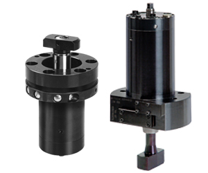
The swing sink clamping elements consist of the housing which accommodates the swing mechanism for the piston, inductive proximity switches for monitoring unclamping, change-over and clamping position, and the piston with the tie rod.
The piston rod is provided with switching contact points which activate the proximity switches in the appropriate positions.
The swing mechanism consists of a guide pin which guides the piston in such a manner that it rotates during part of the stroke. The rotating movement is carried out just before reaching or after leaving the upper piston end position (change-over position). It always rotates to the left, whether the piston is retracting or extending.
Unclamping position
The piston has completely retracted. This makes for easy die changing, as there are no parts projecting above the bed or ram level.
Proximity switch 2S1 monitors this position.
Change-over position for clamping
Pressure is applied to piston side B. The tie rod has moved through the slot of the clamping point and rotates by 45°. Once the rotating movement is completed, the change-over position is reached.
Proximity switch 2S2 monitors this position.
Clamping position
Pressure is applied to rod side A. The tie rod has once again rotated by 45°. Following a linear stroke of 5 mm the tie rod clamps the die.
Proximity switch 2S3 monitors this position.
Unclamping position
Pressure is applied to rod side B. Following a linear stroke of 5 mm the tie rod rotates by 45° into the change-over position.
Proximity switch 2S2 monitors this position.
When pressure is applied to rod side A, the tie rod rotates by 45° and moves into the unclamping position.
Proximity switch 2S1 monitors this position.
Several swing sink clamping elements in one hydraulic circuit will perform different piston movements due to lack of mechanical coupling, different friction of the components and different lengths of piping (there is no synchronous extending of all elements!).
Therefore, the piston movements off ALL swing sink clamping elements in one hydraulic circuit must be fully completed once they have been started, until the change-over position has been reached!
The signals of the proximity switches “Change-over position” 2S2 and of the pressure switches of ALL elements must be available before stroke reversal!
Otherwise the clamping arms may fall out of step, and the swing mechanism may be affected!
2. Possible causes of a failure
The falling out of step of the clamping arms may occur for various reasons.
Clamping arm out of cycle
The most frequent cause for a clamping arm falling out of step is the incorrect approach to the change-over position by all tie rods.
If a tie rod has left the unclamping position but has not yet reached the change-over position, and stroke reversal is initiated, the tie rod will not make another 45° rotation and move into the clamping position but it will rotate backwards and return into the unclamping position. The other tie rods which have moved into the change-over position will rotate, move into the clamping position and clamp the die.
ð One clamping arm has fallen out of step, and its tie rod is in a 90° position to the others.
Disengaging of the overload protection
Another cause for a clamping element falling out of step may be an obstacle impeding free rotation of a tie rod.
This may be an incorrectly positioned die or incorrect design of the clamping point (incorrect clamping slot, no room for rotating).
In order to prevent the swing mechanism from being damaged, the clamping arms are fitted with overload protection. When the rotation is impeded, the guide pin of the swing mechanism may disengage. In this case, a correct position for the tie rod and faultless rotation are no longer ensured.
ð One tie rod has fallen out of step because the overload protection device has disengaged. The inductive proximity switches for monitoring the position of the tie rod will either give no signals at all or signals which are different from those established for the other clamping arms.
Disengaging due to dynamic pressure
The overload protection may also disengage when excessive dynamic pressure has built up in one of the clamping circuits.
Example: If the dynamic pressure at port B increases to more than 50 bar when the tie rod retracts (pressure applied to port A), the sealing friction on the piston increases in such a manner that the overload protection disengages when the tie rod rotates.
Causes of dynamic pressure
Excessive dynamic pressure will build up as a result of inadequate pipe diameters, too long pipe runs, too small a pipe bend radius or too high a delivery from the pump.
When several swing sink clamps are connected in series, dynamic pressures add up and may exceed the critical value of 50 bar. Therefore series connection of swing sink clamps should be avoided.
In the first part the animation shows an element fallen out of cycle of the front cylinder, because stroke reversal has been initiated before it has reached the change-over position.
In the second part of the animation, the overload protection device of the front cylinder disengages during retraction due to excessive dynamic pressure during the rotational movement.
3. Remedial action
Once swing sink clamps have fallen out of cycle, the first step necessary is for the die to be removed from the machine in order to allow access to the tie rod of the clamping element in order to remedy the problem.
Removing the die
Move all swing sink clamps into the unclamping position with the die closed (proximity switch signal 1S1’Unclamping position’).
The clamping element which has fallen out of cycle will clamp the die (depending on the position of the tie rod of this clamping element it is possible that the proximity switch signal 2S3 ‘Clamping position’ will not register, as the clamping point in the piston rod has not activated the corresponding proximity switch).
Synchronizing the tie rods
Switch off the power unit and depressurize all clamping circuits by manual emergency operation of the directional seat valves.
A hexagon head is provided on the rear side of the swing sink clamping element for manual resetting. Use a suitable tool to turn the guide pin until the proximity switch signal 2S3 ‘Clamping position’ lights up *.
Then continue to turn the guide pin by another 90° *. The tie rod will now be in the unclamping position above the clamping slot.
* In these positions it is not necessary that the overload protection engages!
PLEASE NOTE
The guide pin has two positions in which it is engaged, these being staggered by 180°. When turning the guide pin it may be necessary that the overload protection either engages or disengages.
Disengaging moment:
Type 2154 10 Nm
Type 2155 / 2235 20 Nm
Type 2156 / 2237 30 Nm
Switch on the power unit. The command “Unclamp” causes the tie rod to move into the unclamping position.
The die can then be removed.
Engaging the overload protection device
Now turn the tie rod manually (hexagon socket on the clamping head) using a suitable tool until the overload protection engages.
When all tie rods are in the same position and the proximity switch signal 2S1 ‘Unclamped’ registers for all swing sink clamping elements, the problem is remedied.
Resetting an element
If the proximity switch signal 2S1 ‘Unclamped’ does not register for the clamping element that has fallen out of cycle, or if the tie rod is not in the same position as the other ones, the tie rod must be reset to match the cycle of the other clamps.
Switch on the power unit. Move all tie rods manually to the change-over position.
The cylinder which has fallen out of cycle must be blocked in the change-over position. A blank should be used for this purpose (see animation).
If a blank cannot be used, the clamp concerned can be separated from the hydraulic system. To do this, remove all hydraulic pipes from the clamp and close the ports.
Retract and extend all swing sink clamps until a uniform position has been reached.
Functional test
Remove the blank or reconnect the hydraulic system and run the complete clamping and unclamping cycle. Check the elements for synchronous movement and the proximity switches for correct signals.