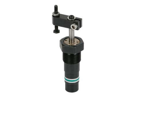
Mini Swing Clamps with Sturdy Swing Mechanism
double acting, max. operating pressure 150 bar

Hydraulic swing clamps are used for clamping of workpieces, when it is essential to keep the clamping area free of straps and clamping components for unrestricted workpiece loading and unloading.
Mini swing clamps are particularly suitable for machining of thin-walled workpieces, which require only little clamping forces.
Mini swing clamps are an interesting alternative for pneumatic clamping elements, since they require less space.
This double-acting mini swing clamp works as pull-type cylinder where a part of the total stroke is used to swing the piston.
Clockwise and counterclockwise versions are available with an swing angle of 90, 60 and 45 degrees. The 0 degree version can be used as push and pull-type cylinder with anti-rotation piston.
- 10
- 25
- 50
| Item no. | CAD data | functioning | piston diameter [mm] | rod diameter [mm] | max. pulling force [kN] | |
|---|---|---|---|---|---|---|
|
Item no.
|
CAD data
|
Properties
| ||||
|
Item no.
|
CAD data
|
Properties
| ||||
|
Item no.
|
CAD data
|
Properties
| ||||
|
Item no.
|
CAD data
|
Properties
| ||||
|
Item no.
|
CAD data
|
Properties
| ||||
|
Item no.
|
CAD data
|
Properties
| ||||
|
Item no.
|
CAD data
|
Properties
|
- 10
- 25
- 50
| Item no. | CAD data | Description |
|---|---|---|
|
Item no.
|
CAD data
|
Description
Built-in housing
for swing clamp 1848-1XX
pipe thread G1/8
as per data sheet B1.848
|
|
Item no.
|
CAD data
|
Description
Clamping arm, complete
for mini swing clamp 1848-1XX
as per data sheet B1.848
|
|
Item no.
|
CAD data
|
Description
Clamping strap assembly, complete
for mini swing clamp 1848-1XX
as per data sheet B1.848
|
|
Item no.
|
CAD data
|
Description
Fixing flange, complete
for swing clamp 1848-1XX
with O-ring and screws
as per data sheet B1.848
|
|
Item no.
|
Description
Socket head cap screw M3 x 8 mm
with low head, 8.8
as per data sheet B1.848
|
|
|
Item no.
|
Description
Disk 3.2 DIN 7349
Ø 9 x 1 mm
as per data sheet B1.848
|
Take advantage of the free benefits of our login area:
- CAD data download
- Download operating instructions
Welcome back! Log in to your already existing user account.