Work Supports automatically adjust to the proper height for supporting a workpiece, then lock securely to become fixed rests. Fluid-advanced Work Supports provide extra loading clearance and are ideal for workpieces that are too light to depress a spring-loaded plunger. The threaded-body Work Support shown here has a very low height, and provides many plumbing options, including manifold mounting.
Available in one size, with inch or metric threads. Choice of two versions: Type 1 with side BSPP port and bottom O-ring port, or Type 2 with bottom BSPP port. Load capacity at 7250 psi: 4500 lbs
Support Action – Fluid Advanced
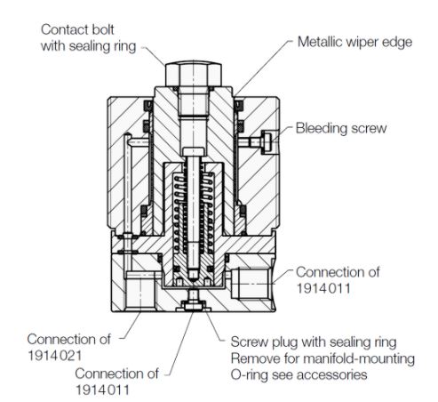
Plunger is normally retracted for clear workpiece loading and unloading. Applying fluid pressure gently advances the plunger to the workpiece, where it contacts with light spring force. As fluid pressure increases, the precision sleeve grips the plunger, locking it securely. The plunger retracts again when pressure is released. Locking height is repeatable within +/-.0002″. Such excellent repeatability is possible because of two design features: 1) a precision sliding-fit pressure sleeve holds the plunger absolutely vertical even while unlocked, avoiding any inaccuracy due to locking a tilted plunger, and 2) locking force is entirely radial, so the plunger remains absolutely stationary during the locking process.
Design Considerations
If the workpiece is light enough that plunger contact could lift it, use a Sequence Valve to delay advancing the work support until after the workpiece is clamped. Do not exceed maximum fluid flow rate in table; otherwise the support could lock prematurely before the plunger is fully extended. Do not use the plunger to lift loads, or support side loads. The support plunger must always be protected against penetration of contaminants by the plastic plug furnished, or a contact bolt (order separately).
When supporting underneath a clamp, use a Sequence Valve to delay clamping until the Work Support has reached sufficient load capacity to resist the clamping force. Support load capacity should be at least 2 times clamping force at all times, to resist not only static clamping force, but also dynamic forces due to clamping-arm momentum and machining forces.
Mounting and Fluid Supply
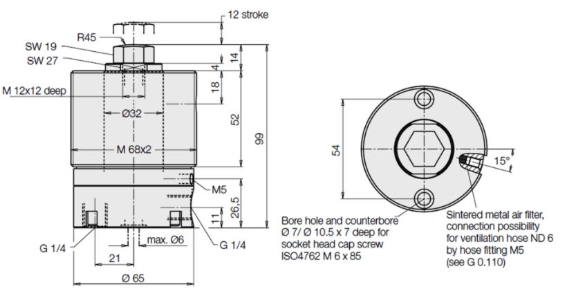
Several possible mounting methods: 1) fasten to fixture with two socket-head cap screws; 2) mount through a tapped hole in the fixture plate, securing with a lock ring; 3) mount through a bored hole in the fixture plate, securing with two lock rings. The manifold-mounted version can also be embedded in a bored hole and fastened with two socket-head cap screws, with fluid supplied through a drilled passage underneath (provide sufficient clearance for the Port Plug).
These Work Supports are available in two versions:
Type 1 Side 1/4″ BSPP port and bottom O-ring port
Type 2 Bottom 1/4″ BSPP port only.
For optional manifold mounting, order Type 1 and use the O-ring port underneath instead of the standard port. Unscrew the sealing plug in the O-ring port and install a CLR-3000-347 O-ring (also install a CLR-810-F Port Plug in the 1/4″ BSPP port). Do not use NPT fittings.