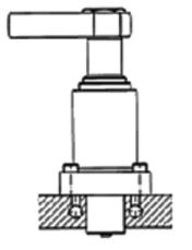
Automation Swing Clamp – Flange Base
3000 to 7250 psi max
Features
- available in three sizes
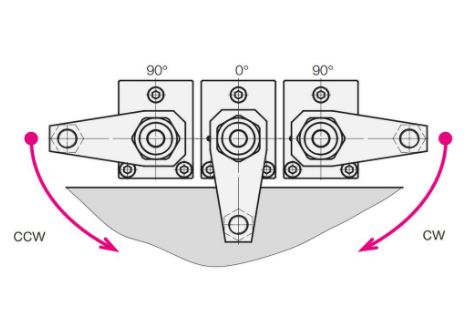
- choice of clockwise, counterclockwise, or zero° swing
- standard fittings or manifold mounting
- clamping force at 7250 psi with a pivoting clamping arm
Check Price & Availability on CarrLane.com


Special series of double-acting Swing Clamps designed for automated high production. Flange-base version provides many plumbing options, including manifold mounting. Reinforced swing mechanism ensures positive arm position. Extended helix rod for built-in pneumatic or electrical position-monitoring capability. Automation-type clamps are a further development of our proven Swing-Clamp line to improve safety in process-linked clamping systems.
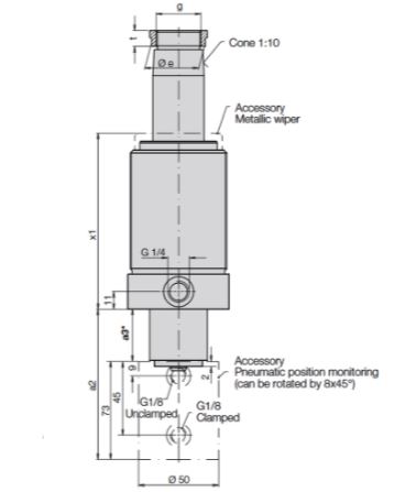
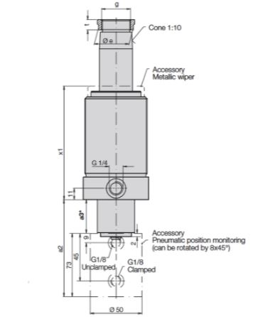
Version 1 – standard fittings Version 2 – Manifold Mounting
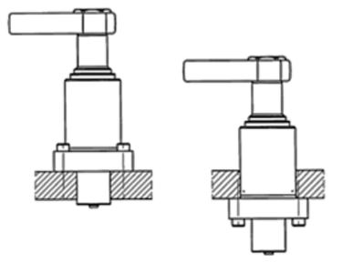
Several possible mounting methods: 1) fasten to top of fixture plate with four socket-head cap screws inserted through the flanged base from above; 2) Mount through a bored hole in the fixture plate, fastening with four socket-head cap screws inserted through the flanged base from below; 3) Mount through a tapped hole in the fixture plate, securing with a lock ring; 4) Mount through a bored hole in the fixture plate, securing with one or two lock rings.
Clamping Arms
Order clamping arm separately – see clamping accessories. Order clamping arm separately. Maximum allowable operating pressure depends on the type of arm selected. Choose a Pivoting Clamping Arm for 7500 psi max (requires a rear support), a Gooseneck Clamping Arm for 5000 psi max, or a Long Clamping Arm for 3000 psi max. Longer, custom clamping arms will further reduce allowable operating pressure, inversely proportional to arm length.
Optional Position Monitoring
The helix rod protrudes through the clamp’s bottom cover, allowing pneumatic or electrical control of piston position outside the chip and coolant area. As an accessory, a pneumatic position control control is available, and is shown attached to the bottom of the clamp in the photo. A brass control slide is displaced in a stainless housing. The slide opens and closes bore holes, so that a pressure switch or differential pressure switch can signal the position as “clamped” or “unclamped”. It is also possible to install this control directly in the fixture body by means of drilled air passages.
Optional Metallic Wiper
This optional, additional wiper protects the Viton wiper against physical damage, e.g. by hot chips. These Swing Clamps are ready for mounting the metallic wiper, which consists of a radially floating wiping disk and a retaining disk which is pressed onto the existing collar.