Hydraulic Block Cylinders
single or double acting with and without spring return
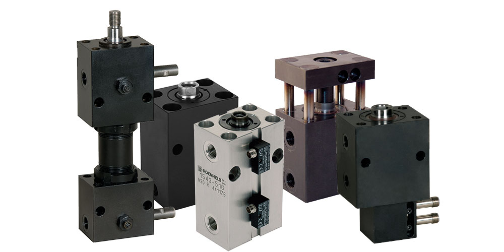
Block cylinders, single or double acting, are made of high alloy steel, bronze alloy and special aluminium alloys. They can be installed in any position and have a max stroke speed of 0.25 m/s, except block cylinders B1.542 and the hydraulic block cylinder B1.590, their piston speed is twice as high with 0.5 m/s. ROEMHELD block cylinders do not leak oil when static. Stroke leakage is at a minimum due to the double piston sealing.
Double Acting Block Cylinders
Double-acting block cylinders can be used universally for all hydraulically-operated linear movements. They generate force in both directions, so they can be used to push or pull. This guarantees a high function safety as well as exactly calculable and repetitive times required for the stroke.
Single Acting Block Cylinders With or Without Spring Return
Single-acting block cylinders can be used on all hydraulically-operated linear movements that do not require a retraction force or where the piston is retracted by an external force. This function can be with or without a spring return, and in both cases when pressurizing the cylinder, the piston extends. When it does have a spring return, after pressure relief, the piston is retracted by spring force. The pressure spring must not only overcome the friction forces, but must also supply the hydraulic oil back to the reservoir. Without a spring return, after pressure relief, the piston must be retracted by an external force. Since no pressure spring is installed, this single-acting block cylinder has the same stroke as the double-acting version with the same length.
If there is a possibility that the cutting lubricants and coolants penetrated through the centered metal air filter into the cylinder’s interior, a vent hose has to be connected and placed in a protected position.
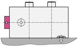
FIXING POSSIBILITIES
Block cylinders have cross holes and/or longitudinal holes for mounting. For mounting of the block cylinders internal threads can be provided instead of the through holes, optionally at the piston rod side or the bottom side.
As an alternative to a support, hydraulic block cylinders can be fitted in the housing with a key way, which transfers the cylinder forces to the base plate surface via a key.
Technical description:
data sheet B1.5091 (single acting)
data sheet B1.5094 (double acting)

INTERMEDIATE STROKES
Stroke limitation by distance bushing: Economical and quickly supplied intermediate strokes
A distance bushing is inserted on the piston rod side in the standard cylinder with the next largest stroke and fastened inside the housing. That means the piston can no longer complete the extending stroke and the stroke is restricted by this internal stop, dependent on the length of the bushing.
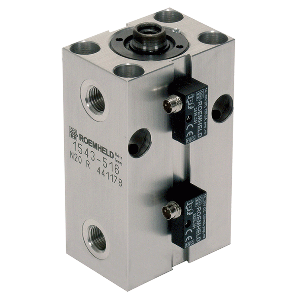
STROKE END CONTROL WITH HIGH-PRESSURE RESISTANT PROXIMITY SENSORS
For every end position, the cylinder housing is given a hole with interior thread, into which a high-pressure resistant, interactive proximity sensor can be screwed. The sensor checks the piston of the cylinder directly. It is sealed on the outside with an O-ring. By means of the switching distance between the sensor and the piston, the switching point can be adjusted to 5 mm
before the end position. Only the end positions of the block cylinder are checked by the high-pressure resistant sensors.
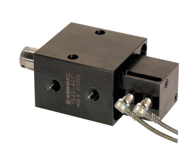
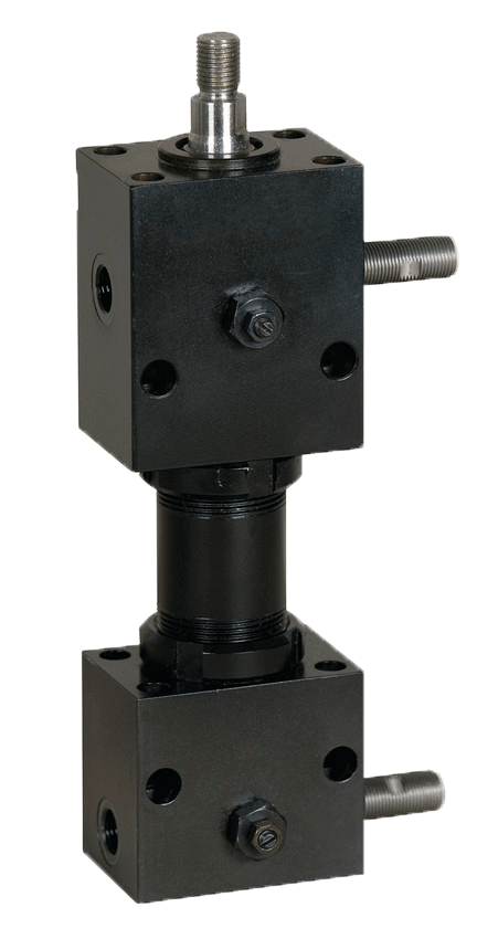
POSITION MONITORING WITH INDUCTIVE PROXIMITY SWITCHES
For a check with commercially available proximity initiators, block cylinders are equipped with a piston rod which passes through the cylinder base. In addition a housing for checking, in which the sensors are fitted and flanged on the cylinder base. The sensors are energized by control cams on the piston rod. The additional housing makes the total length considerably longer but commercially available sensors with M8 x 1 external threads can be used. Because the sensors can be moved, intermediate positions can also be checked.
POSITION MONITORING WITH MAGNETIC SENSORS
A permanent magnet is fixed to the piston, and its magnetic field is detected by a magnetic electronic sensor. With block cylinders, the magnetic sensors are fixed to the outside of the housing in slots running lengthwise.
Advantages of using magnetic sensors are:
- Compact design / minimum space requirement
- Switching points adjustable by moving the sensors along the lengthwise slots
- Possibility of checking several positions, as several sensors can be attached in the two lengthwise slots of the housing, irrespective of the length of the slot or the stroke. In one slot, the minimum distance between the switching points is 6 mm; with two slots it is 3 mm.
HYDRAULIC CONNECTING POSSIBILITIES
Connection with pipe thread
Manifold-mounting with O-ring sealing
Manifold-mounting connection K- with 2 mounting holes
Manifold-mounting connection L – with 4 mounting holes
Manifold-mounting connection S- with 4 mounting holes
Manifold-mounting connection B- with 4 mounting holes


| Data Sheet – B1.5091
|
|
| Data Sheet – B1.5094
|
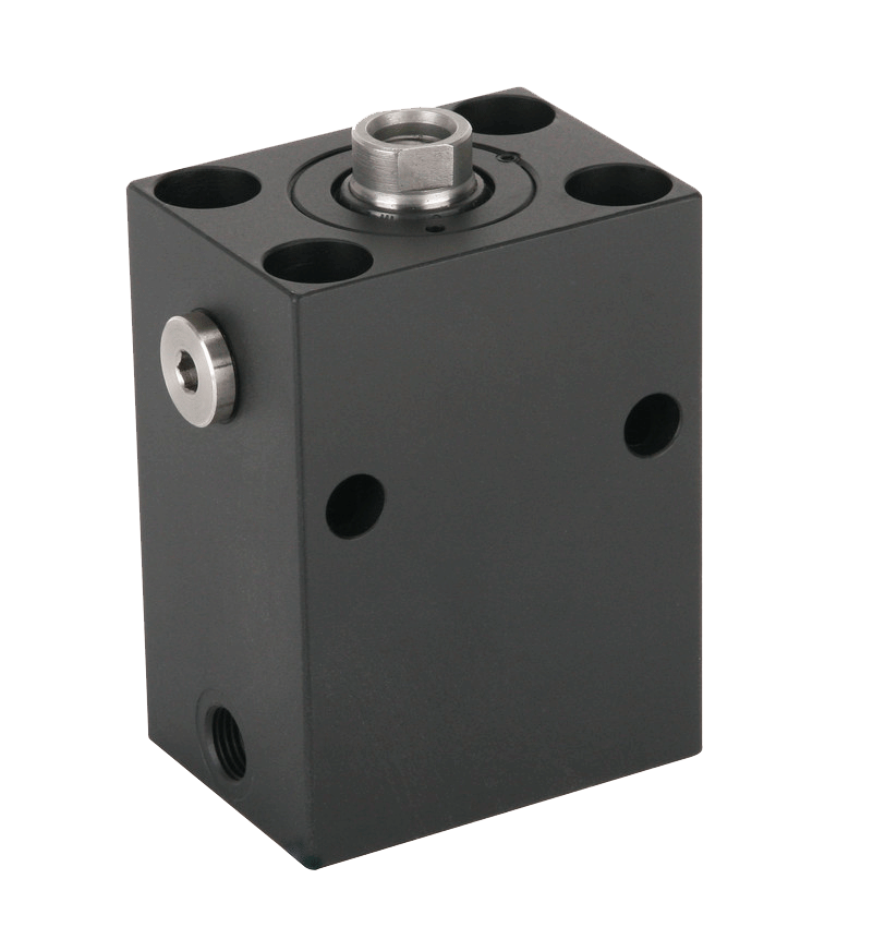
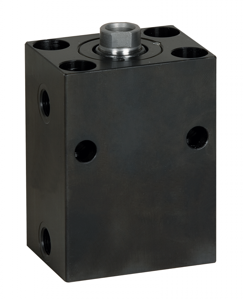
Block Cylinder
double acting, max. operating pressure 500 bar. Force to push at max pressure 1,570 kN.
|
| NEW
|
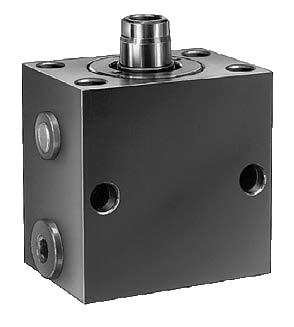
Block Cylinder S
double acting, max. operating pressure 250/500 bar. Force to push at max pressure 251.3 kN. The block cylinders S are equipped with the latest sealing technology, so that optimally adapted versions are available depending on the operating pressure (250 or 500 bar), temperature and hydraulic fluid. |
| Data Sheet – B1.542
|
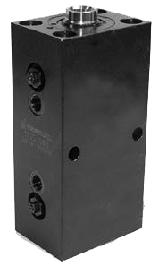
Block cylinder piston rod with exterior thread
double acting, max. operating pressure 500 bar. Force to push at max pressure 155.9 kN. Block cylinders with piston rod with external thread can be equipped with a spherical bearing (accessory). Bearing flanges with rod end bearing are available for fixing at the cylinder bottom. Rod end bearings can be screwed and fixed onto the piston rod. |
| Data Sheet – B1.570
|
Pull-type cylinder
single acting, max. operating pressure 500 bar. Force to push at max pressure 235 kN. |
Data Sheet – B 1.520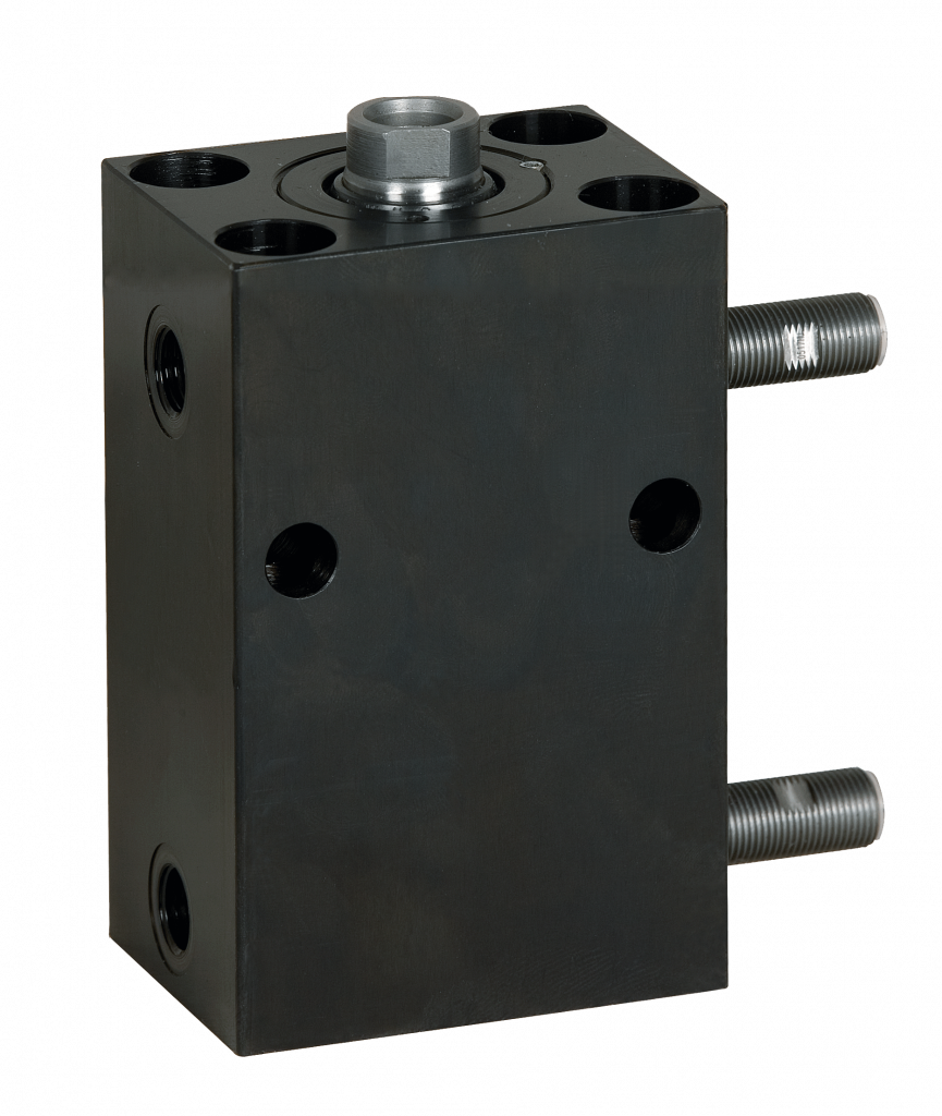 |
Block cylinder for stroke end control
double acting, max. operating pressure 500 bar. Force to push at max pressure 392 kN. The stroke end control supplies the required information about the position of the piston. Control is made by pressure-proof sensors, which are fixed at the corresponding stroke end of the cylinder piston in the body |
| Data Sheet – B1.530
|
Block cylinder with adjustable stroke end cushioning
double acting, max. operating pressure 500 bar. Force to push at max pressure 392 kN. The stroke end cushioning throttles the flow rate in the last millimeters of the stroke (e.g. 8 mm) and reduces the piston speed and the energy in the end positions. The stroke end cushioning is adjustable and the cushioning effect can be adapted to the corresponding application. In addition, both end positions can be separately adjusted. |
| Data Sheet – B1.552
|
Block cylinder with extended piston rod
double acting, max. operating pressure 500 bar. Force to push at max pressure 610 kN. The piston is equipped with a rod of diameter 10 mm that protrudes at the cylinder bottom. At this rod the customer can fix a control cam that is used to operate any limit switch or sensor. |
| Data Sheet – B1.554
|
Block cylinder with aluminium or bronze housing for magnetic sensors
double acting, max. operating pressure 350 bar. Force to push at max pressure 109.2 kN. At maximum operating pressure, block cylinders with aluminium housings are restricted to 350 bar and are not suited to abrupt stresses, which occur, for example, with punching and cutting processes. For such applications, block cylinders with bronze housing are suitable. The bronze housings have a high strength and can be used with abrupt stresses, which occur, for example, with punching and cutting processes |
| Data Sheet – B 1.7384
|
RM Mini Slide with optional position monitoring
|
| Data Sheet – B1.590
|
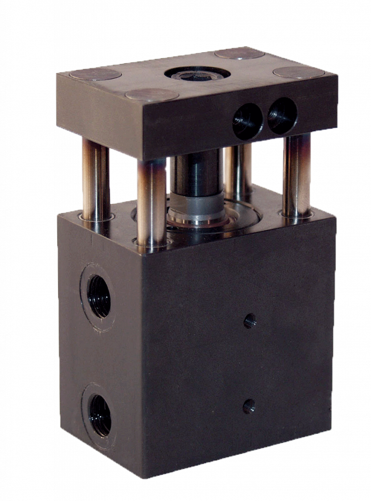
Hydraulic block cylinder design with tube
double acting, max. operating pressure 250 bar. Force to push at max pressure 127.7 kN. The hydraulic block cylinder as linear drive combines the advantages of two series, hydraulic cylinders with long strokes and optional stroke end cushioning, and block cylinders with diverse fixing and oil supply possibilities and optional stroke end control. The two cylinder heads in block form are connected by a HP tube, in which the piston is |
| Data Sheet – B 1.5401
|
Built-in elements piston and threaded bushing
double acting, max. operating pressure 500 bar. Force to push at max pressure 392 kN. Built-in elements are directly integrated in the fixture body. Such created cylinders can be used as push or pull cylinders. |
| Data Sheet – B1.5601
|
Built-in elements piston with anti-rotation piston
double acting, max. operating pressure 350 bar. Force to push at max pressure 68.7 kN. Built-in elements are directly integrated in the fixture body. Such created cylinders can be used as push or pull cylinders. The built-in elements consist of piston and threaded bushing. The piston is inserted into the location hole of the fixture. Then the built-in bushing is screwed into the fixture body. The bushing is let-in flush to the housing. |


Application Examples
TOOLS FOR FABRICATION OF AN AUTOMOTIVE COMPONENT
5 block cylinders operate these core-pullers for the required dimensional accuracy of the complex shaping of this elbow tube with two additional tube connections.
TOOLS FOR FABRICATION OF CONNECTING ELEMENTS FOR STROLLERS
The core-pullers for injection molding connecting components made out of plastic materials are inserted and retracted by aluminium block cylinders B1.554 for fabrication in exact position.
TOOL FOR FABRICATION OF MOBILE PHONE HOUSINGS
The exact shaping of the inlet for the later installation of the microphone is made during the injection process by dies, which is operated by aluminium block cylinders with magnetic sensors.

OPERATING CORE PINS
In the figure the core cylinder is located in the main core. The position monitoring supplies the required information of the core pins position.
The connection of cylinder and core puller should be effected by means of a coupling pin because core pullers are usually self-guiding.
OPERATING A SLIDE IN A DEEP-DRAW MOLD
If it is impossible to install a block cylinder directly due to force or space restrictions, the block cylinder with spherical bearing might be an alternative.
The figure shows the operation of a slide in a deep-draw mold for a container. The position monitoring supplies the required information about the position of the connecting part.
OPERATING CORE PULLER PLATES
The figure shows an item which is made in three versions. The core-pins are driven into the corresponding position by two independently-controlled core puller plates.
Version A core puller plate 1 actuated
Version B core puller plate 2 actuated
Version C core puller plates 1+2 actuated
The core puller plates drive against fixed stops in the front and back position and are controlled by proximity switches in both positions. This enables an integration into the control of the mold carrier. The figure shows version A;
Core puller plate 1 is actuated.
Core puller plate 2 is not actuated.
The building height of the foam mold is limited by the mold carrier. Due to the small and compact dimensions of the block cylinders the core puller plates could be installed in a space-saving way.